Finite Element Analysis for Weldment Design: How FEA Reduces Weight Without Compromising Strength
In today’s competitive marketplace, manufacturers are constantly challenged to do more with less—less weight, less material, and less cost—without sacrificing performance or safety. Welded assemblies are at the heart of countless products, from machine frames and robotic tooling to heavy-duty enclosures and transportation equipment. Each one must strike the right balance between strength, weight, and durability. That’s where Finite Element Analysis (FEA) comes in.
At Seifert Engineering, we use FEA to help our customers create virtual prototypes of their weldments. This process allows us to simulate how an assembly will perform under real-world conditions, pinpoint stress concentrations, and explore redesign options before the first piece of steel is ever cut. The result? Lighter, stronger, and more efficient designs that save time and reduce costs.
Traditional Weldment Design vs. FEA Optimization
Traditionally, weldments have been designed with large safety factors. While this “better safe than sorry” approach works, it often leads to heavier structures than necessary. Extra weight increases material costs, makes handling and installation more difficult, and can even limit performance in applications where mobility or efficiency is critical.
With FEA, engineers don’t need to rely on rules of thumb or oversizing. Instead, we can simulate exact conditions—stress, vibration, temperature, and more—to see how the weldment will behave. This digital stress test provides valuable insights into where material is truly needed for strength and where it can be safely reduced.
Stress Risers in Weldments: What FEA Reveals
One of the biggest advantages of FEA is its ability to reveal stress risers—the areas where failures are most likely to occur. In welded assemblies, these often include:
- Weld geometry and roots, where the shape changes dramatically.
- Connection points with bolts, pins, or fasteners.
- Transitions in material thickness, where loads aren’t evenly distributed.
- Corners and cutouts, which concentrate stresses.
By identifying these critical zones early in the design process, we can reinforce them strategically while trimming away unnecessary weight in low-stress regions.
FEA Meshing Strategies and Boundary Conditions for Weldments
Running an FEA model isn’t just about clicking “analyze.” The quality of the results depends heavily on how the simulation is set up—particularly meshing and boundary conditions.
- Meshing strategies: The mesh is the network of small elements used to represent the weldment. Finer meshes in high-stress areas capture detail more accurately, while coarser meshes in low-stress areas speed up calculations. The right balance ensures reliable results without unnecessary computation time.
- Boundary conditions: These define how the assembly is constrained and loaded in the real world. Properly applying loads, supports, and connections is critical for making the simulation behave like the actual structure.
At Seifert Engineering, our team’s experience ensures that each simulation is built on solid fundamentals, giving our customers confidence that the results will reflect reality.
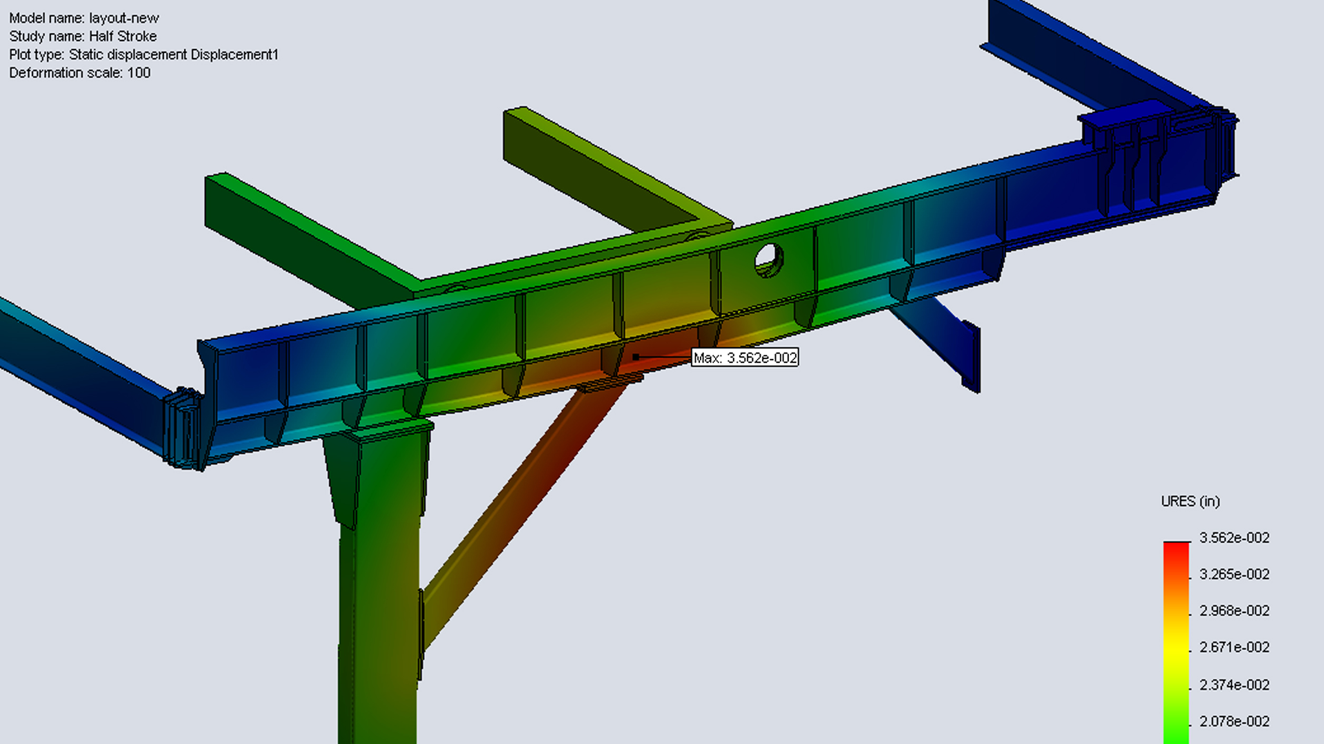
Visualizing Stress and Making Better Design Decisions
One of the most powerful aspects of FEA is its ability to visualize stress concentrations through clear, color-coded plots. Instead of guessing, customers can literally see where their design is strongest and where it needs attention. These visual insights help guide collaborative conversations about redesign—whether that means adjusting weld sizes, changing materials, or redistributing loads.
This process doesn’t just reduce weight and improve efficiency; it also builds confidence. Customers know that their design has been tested, validated, and optimized before fabrication begins.
Partnering for Better Weldment Designs
FEA is more than a software tool—it’s a way of thinking about design. At Seifert Engineering, we see it as an opportunity to partner with our customers. By combining simulation with our deep engineering expertise, we help companies bring better products to market faster, with fewer prototypes and lower development costs.
Whether you’re working on a new weldment design or looking to improve an existing assembly, our team can help you optimize for strength, efficiency, and manufacturability. With FEA, you don’t have to choose between lightweight and durable—you can have both.
👉 Explore Seifert Engineering’s FEA services to see how simulation can support your next project.
FAQs on Weldment Design and FEA
Why use FEA for weldment design?
FEA allows engineers to simulate stress and loading conditions, optimize material usage, and reduce weight without compromising strength.
What are common stress risers in welded assemblies?
Weld geometry, roots, fastener connections, material transitions, and cutouts are the most common areas where stress concentrates.
Can FEA replace physical prototypes?
Not entirely, but it significantly reduces the number of prototypes needed by identifying issues earlier in the design process.